en
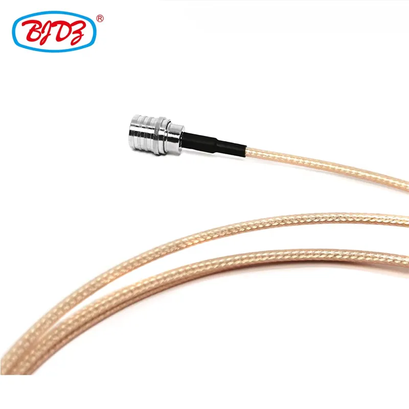
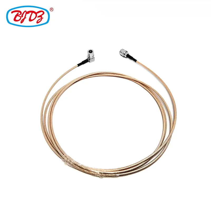
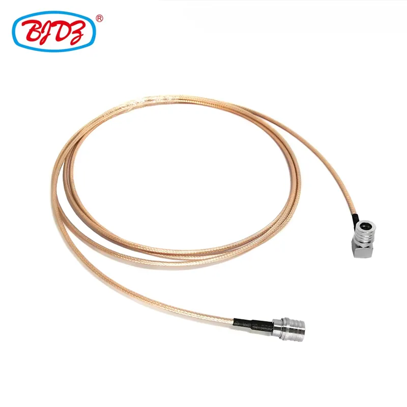
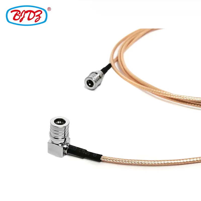
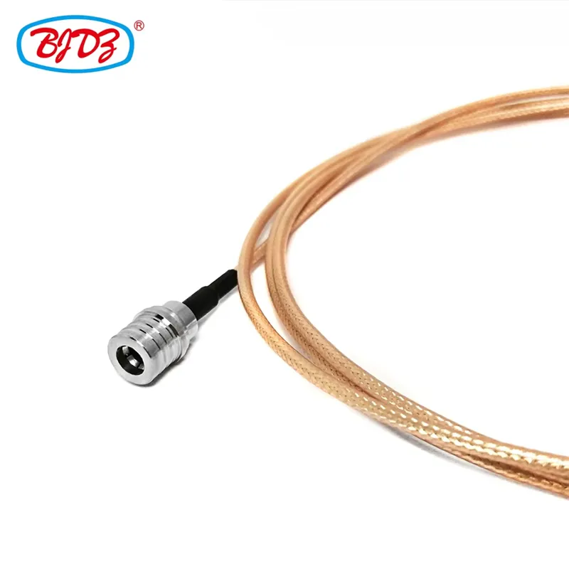
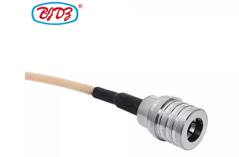
The QMA Male to QMA Male Right Angle RG316 Jumper Cable Assembly is a high-frequency RF interconnect solution designed for space-constrained environments where board-to-board, module-to-antenna, or rack-to-rack connections demand compact routing and reliable signal integrity. Featuring a straight QMA male plug on one end and a 90° right-angle (elbow) QMA male plug on the other, this assembly provides engineers with the flexibility to route cables around tight enclosures, PCB edges, or equipment panels without exceeding minimum bend radius limits.
Built on RG316/U ultra-flexible coaxial cable with FEP dielectric and dual silver-plated copper braid shielding, this jumper maintains stable 50-ohm impedance across DC–6 GHz frequency ranges. The QMA quick-lock snap-on interface enables tool-free mating in seconds, offering superior vibration resistance compared to traditional threaded SMA connectors — making it ideal for UAV avionics, telecom base stations, test fixtures, and industrial IoT gateways.
Manufactured at Zhenjiang Binjiang Electronic Co., Ltd., this assembly is produced on automated crimping lines with 100% VNA-tested performance verification, ensuring every unit meets strict return loss and insertion loss specifications before shipment.
Parameter | Specification | ||
Impedance | 50 Ohm | ||
Connector A | QMA Male Plug • Straight • Quick-lock snap-on • Brass body, gold-plated • PTFE dielectric | ||
Connector B | QMA Male Plug • 90° Right Angle (Elbow) • Quick-lock snap-on • Brass body, gold-plated • PTFE dielectric | ||
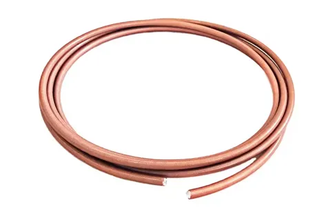
Cable Type | RG316/U • Ultra-flexible • FEP dielectric • Silver-plated copper braid shield • FEP jacket | ||
Cable OD | 2.5 mm (0.098") | ||
Frequency Range | DC to 6 GHz | ||
VSWR | ≤ 1.25:1 (DC – 3 GHz) / ≤ 1.35:1 (3 – 6 GHz) | ||
Insertion Loss | ≤ 0.8 dB/m @ 1 GHz / ≤ 1.5 dB/m @ 3 GHz | ||
Mating Cycles | ≥ 500 | ||
Temperature Rating | -55°C to +165°C (FEP cable jacket) | ||
Bend Radius | 12.5 mm (0.49") minimum static | ||
Compliance | RoHS 2.0, REACH, CE, UL | ||
Parameter | Value | ||
Center Conductor | 7×0.17 mm Silver-Plated Copper Wire (Stranded) | ||
Dielectric | Solid PTFE (Polytetrafluoroethylene), 1.52 mm OD | ||
Shield 1 | Silver-Plated Copper Braid (>95% coverage) | ||
Shield 2 | Silver-Plated Copper Braid (>95% coverage) | ||
Jacket | FEP (Fluorinated Ethylene Propylene), Brown/Transparent | ||
Velocity of Propagation | 69.5% | ||
Capacitance | 96 pF/m | ||
Attenuation @ 400 MHz | 0.55 dB/m | ||
Attenuation @ 900 MHz | 0.85 dB/m | ||
Attenuation @ 2.4 GHz | 1.45 dB/m | ||
Attenuation @ 5.8 GHz | 2.50 dB/m | ||
Industry / Field | Specific Use Case | ||
Drones & UAVs | Internal RF routing from flight controller telemetry module to fuselage-mounted antenna, where right-angle exit avoids cable strain near PCB edges. | ||
Telecom Base Stations | Jumper connections between RRH (Remote Radio Head) transceiver boards and panel-mounted antenna ports in confined enclosure spaces. | ||
Test & Measurement | Bench-top test fixtures linking VNA (Vector Network Analyzer) ports to DUT (Device Under Test) evaluation boards with limited vertical clearance. | ||
Industrial IoT Gateways | Connecting internal Wi-Fi/LoRa/Zigbee modules to external RP-SMA or QMA bulkhead connectors on ruggedized metal enclosures. | ||
Medical Devices | Compact RF interconnects in portable diagnostic equipment where space, weight, and bend radius are tightly constrained. | ||
Aerospace & Defense | Avionics rack-to-rack patching and satellite communication terminal internal wiring with high-vibration and temperature requirements. | ||
This assembly pairs a straight QMA male connector with a 90° right-angle QMA male connector, solving a common engineering challenge: connecting a vertically oriented RF port (e.g., a module's top-mounted SMA/QMA jack) to a horizontally constrained path. The elbow connector redirects the cable exit by 90°, eliminating sharp bends and reducing mechanical stress on both the cable and the PCB-mounted receptacle.
The QMA push-on mechanism provides a secure, vibration-proof connection without rotational torque. Unlike threaded SMA connectors that can loosen under continuous vibration (common in drone platforms and industrial machinery), the QMA's internal spring-loaded sleeve locks firmly into place and requires only a simple pull-back to release — enabling rapid field maintenance and reducing assembly time on production lines.
RG316/U is selected for its exceptional flexibility and wide temperature tolerance. The stranded silver-plated copper center conductor and dual silver-plated copper braid shields allow repeated bending and routing in tight spaces without signal degradation. The FEP (fluorinated ethylene propylene) jacket withstands soldering temperatures and harsh chemical environments, making it suitable for aerospace and industrial applications.
Every junction — from the RG316 center conductor to the QMA contact pin, and from the braid to the connector body — is engineered to maintain continuous 50-ohm impedance. This minimizes reflections and standing waves, ensuring optimal VSWR performance critical for high-data-rate wireless links and sensitive receiver front-ends.
All QMA connector bodies and center contacts feature gold plating over nickel underplate, providing ultra-low contact resistance, corrosion immunity, and long-term reliability even in high-humidity or outdoor deployments.
1. Precision Crimping: Automated crimp stations calibrated specifically for RG316 ferrule dimensions ensure gas-tight, mechanically robust connections between cable braid and QMA connector body.
2. Gold-Plated Contact Surfaces: Provides ultra-low contact resistance and superior corrosion resistance across the full operating temperature range (-55°C to +165°C).
3. 100% VNA Electrical Testing: Every assembly is swept on a calibrated Vector Network Analyzer to verify Return Loss (VSWR) and Insertion Loss from DC to 6 GHz. Units failing to meet ≤1.25:1 VSWR @ 3 GHz are rejected.
4. Mechanical Pull-Test: Random samples from each batch undergo strict axial pull tests (per IEC 61169-16) to validate crimp integrity and cable retention force.
5. Thermal Cycling: Sample batches undergo -55°C to +165°C thermal shock testing to verify solder joint and crimp stability under extreme temperature transitions.
Option | Choices | ||
Cable Length | 10 cm, 20 cm, 30 cm, 50 cm, 100 cm, Custom lengths available | ||
Connector A Orientation | Straight (Standard) / 90° Right Angle | ||
Connector B Orientation | 90° Right Angle (Standard for this SKU) / Straight | ||
Heat Shrink Boot | Optional adhesive-lined heat shrink for enhanced strain relief and moisture sealing | ||
Cable Jacket Color | Brown (Standard RG316) / Black / Custom colors | ||
Labeling & Packaging | Custom part-number labels, anti-static PE bags, ESD-safe trays, or bulk packaging | ||
Q1: Why use a right-angle QMA connector instead of bending a straight connector's cable?
Forcing a 90° bend immediately after a straight connector exceeds the cable's minimum bend radius, causing impedance discontinuities, increased VSWR, and potential center-conductor migration. A factory-built right-angle QMA connector provides a precision-engineered, impedance-matched 90° transition inside the connector body, preserving signal integrity and mechanical reliability.
Q2: What is the advantage of QMA over SMA for this right-angle jumper?
The QMA's push-on quick-lock mechanism requires no rotational torque for mating, making it ideal for right-angle applications where tool access is limited. Additionally, the snap-on interface is inherently more vibration-resistant than SMA's threaded coupling, reducing the risk of connection failure in dynamic environments.
Q3: Can RG316 handle 5.8 GHz FPV or Wi-Fi signals?
Yes, but with caveats. At 5.8 GHz, RG316 attenuation is approximately 2.5 dB/m. For short jumper lengths (10–30 cm), the loss is minimal (0.25–0.75 dB), making it perfectly suitable for internal module-to-antenna connections. For longer runs exceeding 1 meter at 5.8 GHz, consider upgrading to a lower-loss cable such as RG402 semi-rigid or 5D-FB.
Q4: How do I unmating the QMA connector?
Pull back the outer sliding sleeve on the QMA male plug while pulling the connector straight out from the jack. Never twist, rotate, or pry the connector, as this can damage the internal locking mechanism or the PCB-mounted receptacle.
Q5: Is this assembly suitable for outdoor or high-vibration environments?
Yes. The FEP jacket provides UV and chemical resistance, and the QMA snap-lock mechanism is inherently vibration-proof. For exposed outdoor connections, we recommend adding optional adhesive-lined heat shrink boots at both connector junctions for IP67-level moisture sealing.
1. QMA Quick-Lock Mating: Align the QMA male plug with the jack and push straight in until you feel/hear a distinct click. Verify retention by gently pulling the connector body (do not pull the cable).
2. Right-Angle Orientation: Before final mating of the 90° connector, verify the cable exit direction aligns with your intended routing path to avoid post-mating cable stress.
3. Minimum Bend Radius: Maintain at least 12.5 mm (0.49") bend radius on the RG316 cable. Do not kink or flatten the cable during routing.
4. Cable Support: Secure the cable within 5 cm of each connector using a P-clip or foam tape to prevent mechanical load transfer to the solder/crimp joints.
5. Environmental Sealing: For outdoor or high-humidity deployments, wrap connector junctions with self-amalgamating silicone tape or specify factory-applied adhesive heat shrink boots.
6. Storage: Store unused assemblies in sealed anti-static bags with desiccant packs. Avoid prolonged exposure to temperatures exceeding +85°C or direct UV sunlight.
Zhenjiang Binjiang Electronic Co., Ltd. — Precision RF Interconnect Solutions Engineered for Performance.
 English