en
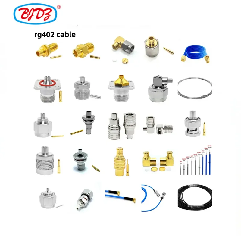
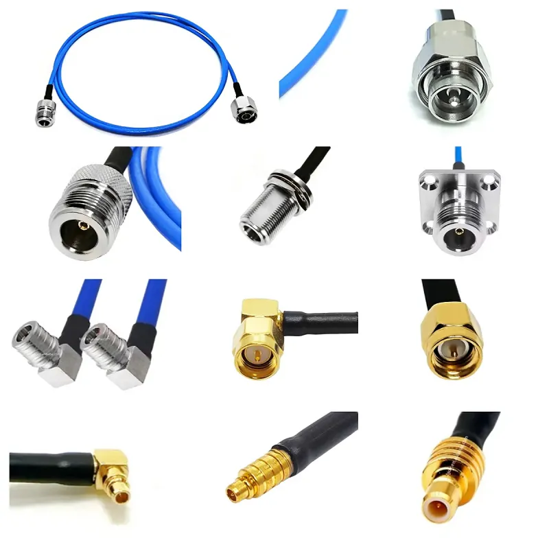

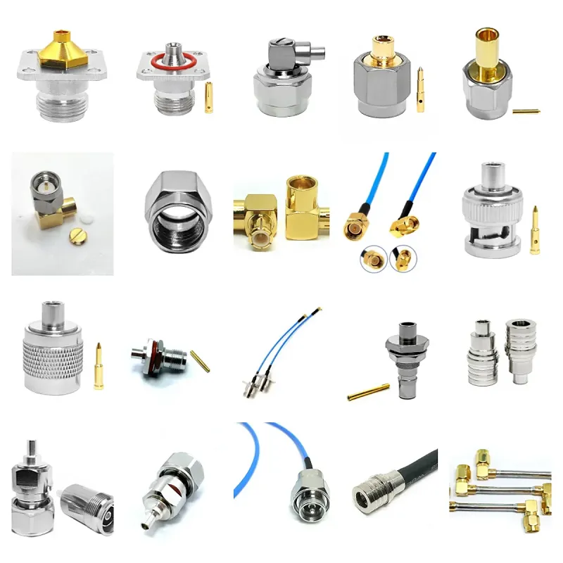
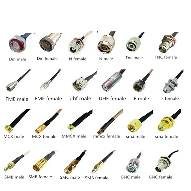
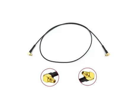
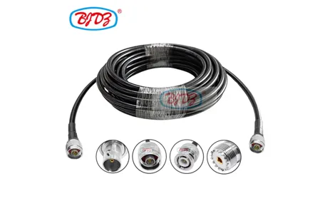
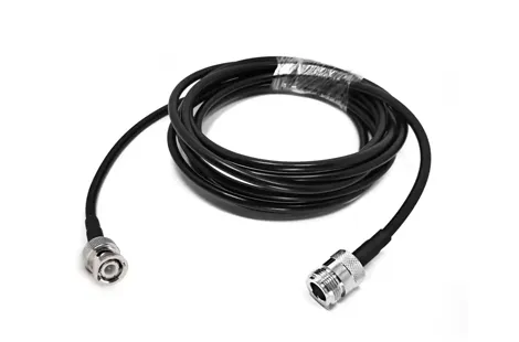
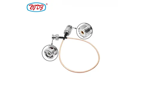
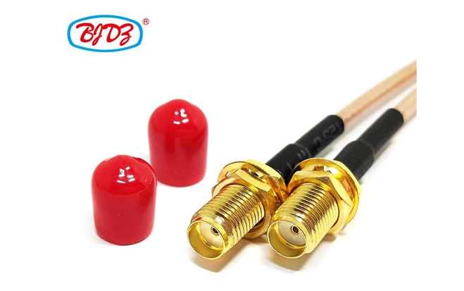
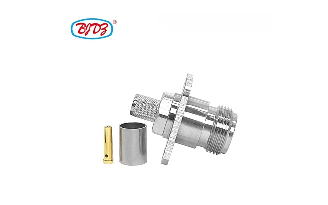
Engineered for industrial, defense, and 5G infrastructure applications, this multi-connector RF pigtail cable assembly integrates nine industry-standard RF interfaces — SMA, N, QMA, BNC, TNC, 4.3-10, MCX, MMCX, and SMB — into a single high-performance RG402/U semi-rigid cable with panel-mount female flange jacks. Designed for seamless integration into base stations, radar systems, test benches, and aerospace avionics, it eliminates adapter clutter while ensuring signal integrity up to 34 GHz.
Key attributes
| Conductor Material | Copper |
| Insulation Material | PTFE |
| Jacket | PVC |
| Number of Conductors | 1 |
| Model Number | Coaxial Connector rg402 Cable Assembly |
| Cable Type | rg405 Coaxial Cable |
| Brand Name | BJDZ |
| Place of Origin | Jiangsu, China |
| Application | RF |
| Plating | Nickel or Tri-Metal plated |
| Material | Copper |
| Insulator | PTFE/Plastic |
| Certificate | CE/FCC/ROHS/ISO9001:2015 |
| VSWR | 1.15+0.02f |
| Vibration | 98m/S2 (10~2000Hz), 10g |
| Frequency Range (MHz) | DC-12.4GHz(semi-rigid cable DC-18 GHz) |
| Max Voltage | 335V max |
| Temperature range | -55~+155°C (PE Cable -40~+85°C) |
| Input Impendence (ohm) | 50 |
| V.S.W.R | 1.15+0.02f |
| Vibration | 98m/S2 (10~2000Hz), 10g |
| Insertion Loss | ≤ 0.15dB/6GHz |
| Withstand Voltage | 1000V rms |
| Working Voltage | 335Vr.m.s at sea level |
| Insulation resistance | ≥5000mΩ |
| Max Input Power (w) | 50 |
| Contact resistance | Center Contact ≤3mΩ |
| Center conductor retention force | 450N |
| Durability | ≥ 500(cycles) |
| Contact resistance | CenterContact ≤3mΩ Outer Contact ≤2.5mΩ |
| Voltage Standing Wave Ratio | Straight ≤ 1.15/6GHz Right angle ≤ 1.25/6GHz |
Packaging and delivery
| Selling Units | Single item |
| Single package size | 111X10X10 cm |
| Single gross weight | 1.00kg |
Lead time
| Quantity (pieces) | Lead time (days) |
| 1 - 1000 | 10 |
| 1001 - 5000 | 15 |
| 5001 - 10000 | 25 |
| > 10000 | To be negotiated |
price
| 50 - 1999 pieces | $3.02 |
| 2000 - 4999 pieces | $1.58 |
| >= 5000 pieces | $1.28 |
Parameter | Specification |
Cable Type | RG402/U — Semi-rigid, 0.086" (2.18mm) OD coaxial cable with silver-plated copper-clad steel center conductor and solid PTFE dielectric |
Impedance | 50 Ω ±2% |
Velocity of Propagation | 69.5% |
Max Operating Frequency | 34 GHz — Certified for full-band operation across all supported connectors |
Insertion Loss (Typical) | 0.25 dB/m @ 0.5 GHz |
Shielding Effectiveness | >90 dB (up to 34 GHz) — 100% copper braid + foil shield |
Outer Jacket | Black PTFE — UV-resistant, chemical-proof, RoHS & REACH compliant, operating range: -55°C to +165°C |
Minimum Bend Radius | 6.35 mm (repeated) / 2.5 mm (single) |
Mating Cycles | ≥500 for all connectors |
Dielectric Withstanding Voltage | 5,000 V RMS |
Connector Types | Male Plug (SMA, N, QMA, BNC, TNC, 4.3-10, MCX, MMCX, SMB) → Female Flange Jack (SMA, N, QMA, BNC, TNC, 4.3-10, MCX, MMCX, SMB) |
Panel Mount Standard | Flange-mounted female jacks with 4-hole mounting pattern — compliant with MIL-STD-348A and IEC 60169-15/16 |
PIM Performance | < -150 dBc (tested per IEC 62037) — Critical for 5G DAS and LTE systems |
Certifications | MIL-C-17, IEC 61169, RoHS, REACH, UL 94 V-0 |
Connector | Max Frequency | Male Plug Use Case | Female Flange Jack Use Case |
SMA | 26.5 GHz | Test equipment, VNA, 5G FR2 | Panel-mounted lab instruments, radar front-ends |
N-Type | 18 GHz | Base station antennas, microwave links | Outdoor enclosures, cell tower RF distribution |
QMA | 6 GHz | Rapid-connect test ports | 5G small cell backhaul units |
BNC | 4 GHz | Legacy test gear, video systems | Industrial control panels, EMI labs |
TNC | 11 GHz | Vibration-prone environments | Military vehicle comms, airborne systems |
4.3-10 | 6 GHz | Low-PIM 5G DAS | Distributed antenna system hubs |
MCX | 6 GHz | Compact IoT modules | Embedded wireless sensors |
MMCX | 6 GHz | Wearable RF devices | UAV payload interfaces |
SMB | 4 GHz | High-density PCB interconnects | Avionics control units |
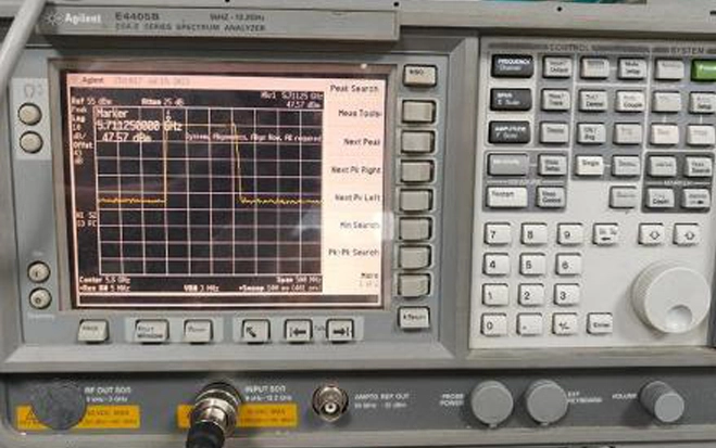
Each connector pair is individually tested for S11/S21 performance using a calibrated VNA. Traceable test reports available upon request.
The female flange jack design is engineered for permanent, vibration-resistant panel integration — unlike bulkhead or cable-end connectors:
No strain on cables — mechanical load is absorbed by the mounting flange
Sealed environmental protection — gasket-ready flange design supports IP67 sealing
Tool-free maintenance — quick disconnect/reconnect without torque wrenches
EMI containment — full 360° shield continuity from panel to connector
Standardized mounting — 4-hole pattern compatible with 1/4" and 6mm panel thicknesses
Ideal for 5G small cell deployments, military radar arrays, and automated test equipment where signal stability under thermal cycling and mechanical shock is non-negotiable.
This assembly eliminates the need for multiple adapters, reducing:
Signal loss from 3–5 dB per adapter cascade
Risk of misconnection or reverse polarity
Inventory complexity for field technicians
Failure points in high-vibration environments
Engineered for OEMs integrating multiple RF subsystems into a single chassis — reduce BOM cost, simplify assembly, and improve MTBF.
5G mmWave Base Stations — Connects FR2 antenna arrays to AAU/RRU with low-PIM flange jacks
Military Avionics — Replaces legacy BNC/TNC bundles in fighter jet radar systems
Satellite Ground Stations — Enables multi-band RF switching with zero signal drift
EMC/RF Test Labs — Eliminates adapter-induced measurement errors during compliance testing
Industrial IoT Gateways — Integrates MCX/MMCX sensors with N-type backhaul links
Distributed Antenna Systems (DAS) — Low-PIM 4.3-10 jacks ensure clean signal distribution
Automotive Radar Calibration — SMA and SMB interfaces for 77GHz sensor validation
Standard Stock: 15cm RG402 length, black PTFE jacket, pre-tested per batch
Custom Options:
Cable lengths: 10cm, 20cm, 30cm, 50cm, 100cm
Jacket colors: White, Red, Blue (for system identification)
Connector combinations: Any male → any female flange pair (select 1 of 81 possible combinations)
Bulk packaging: 25 pcs/box, anti-static ESD bags with individual QR-coded test reports
MOQ: 5 pieces
Lead Time: 2–4 days for standard | 7–10 days for custom configurations
Support: Full test data, MIL-C-17 certification, RoHS/REACH declarations, and application engineering support included
Compatible with Keysight, Rohde & Schwarz, Anritsu, National Instruments, and Tektronix test platforms. Not compatible with Fakra, NMO, or 75Ω systems.
 English