en
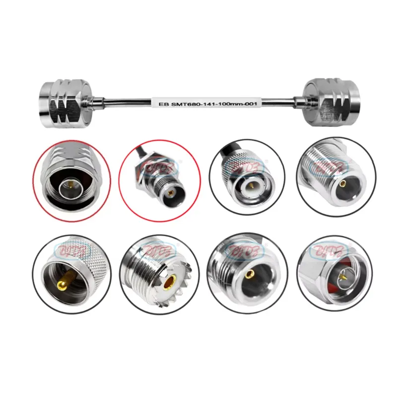
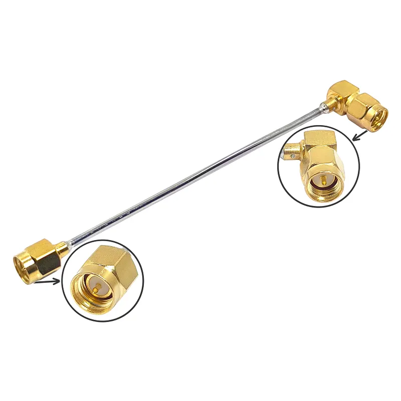
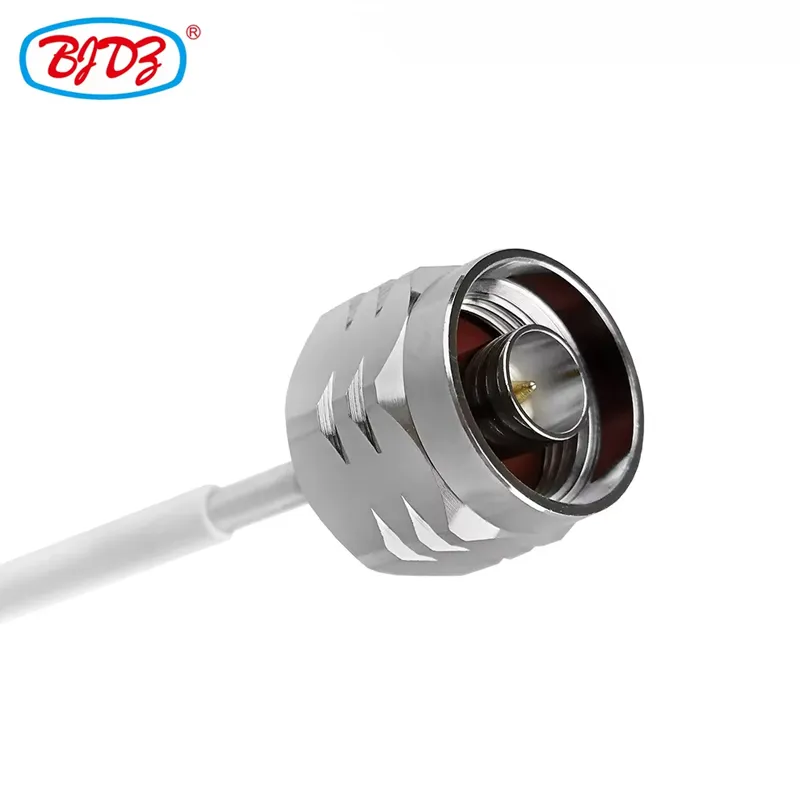
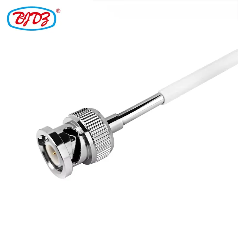
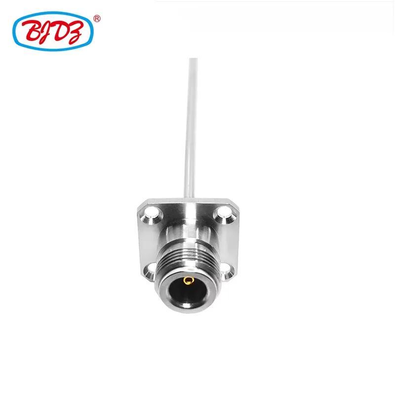
This comprehensive line of semi-rigid RF coaxial cable assemblies is engineered for high-frequency, low-loss applications where signal integrity and physical routing stability are paramount. Utilizing premium copper-plated semi-rigid coaxial cables (RG402, RG405, and 0.086 inch), these assemblies offer superior shielding effectiveness and lower insertion loss compared to standard flexible cables.
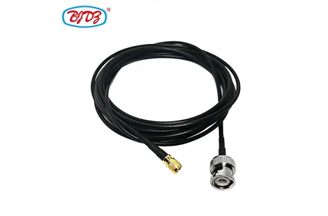
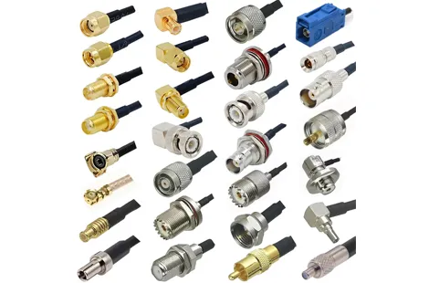
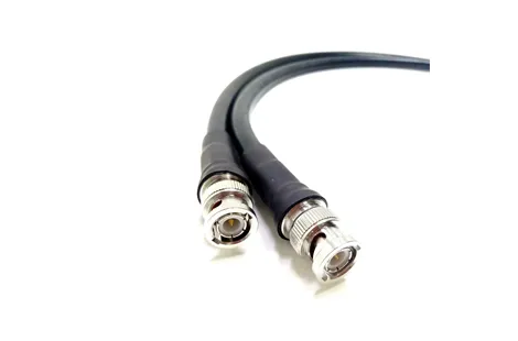
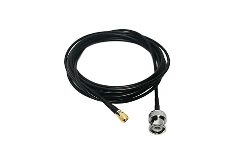
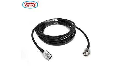
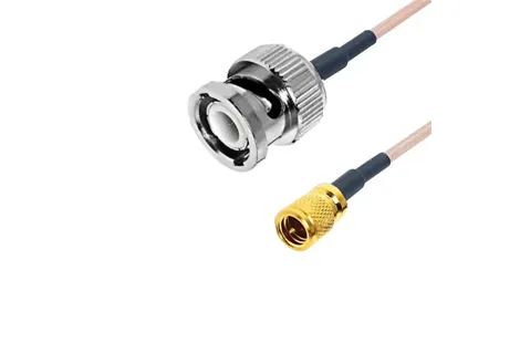
Designed for precision routing, semi-rigid cables can be hand-formed to exact geometries and will hold their shape, making them ideal for internal equipment wiring, aerospace, defense, and high-density RF modules. The assemblies support a wide matrix of industry-standard connectors, including N, SMA, BNC, TNC, and UHF (PL-259/SO-239), and can be terminated to N-Type Panel Mount configurations for secure chassis integration.
Parameter | Specification |
Impedance | 50 Ohm |
Connector Options | N (Male/Female/Panel Mount), SMA, BNC, TNC, UHF (PL-259/SO-239) |
Cable Options | RG402 / 0.141" (OD: 3.58mm) RG405 / 0.086" (OD: 2.19mm) 0.086" Micro Semi-Rigid |
Cable Construction | Center: Solid Copper (Silver-plated) Dielectric: Solid PTFE Outer Conductor: Solid Copper Tube (Copper-plated) Jacket: Optional FEP/PE |
Frequency Range | DC to 18 GHz (RG402/RG405); Up to 26.5 GHz+ (0.086 precision variants) |
VSWR | ≤ 1.10:1 (DC to 6 GHz); ≤ 1.20:1 (6 to 18 GHz) |
Shielding Effectiveness | > 100 dB (Solid tube construction provides near-perfect EMI/RFI rejection) |
Temperature Range | -55°C to +165°C (PTFE dielectric) |
1. Superior Signal Integrity & Shielding
Unlike braided flexible cables, semi-rigid coax uses a solid copper outer conductor. This provides near-perfect shielding (>100 dB), eliminating signal leakage and protecting sensitive RF paths from external EMI/RFI in high-density electronic environments.
2. Formable Routing & Shape Retention
Semi-rigid cables are designed to be bent and shaped by hand (using proper forming tools) to fit exact internal chassis layouts. Once formed, the solid copper tube holds its shape permanently, eliminating the need for cable ties and reducing assembly time.
3. Copper-Plated Solid Conductors
The use of solid copper center conductors and copper-plated outer tubes ensures the lowest possible insertion loss and highest power handling capabilities at microwave frequencies.
4. Versatile Connector Matrix
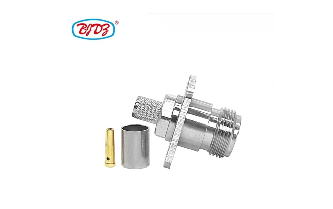
We support custom hybrid assemblies. Route signals from internal micro-components using SMA or 0.086 connectors, transitioning to rugged UHF (PL-259/SO-239) or BNC interfaces, and terminating at the chassis via a secure N-Type Panel Mount jack.
Industry / Field | Specific Use Case |
Aerospace & Defense | Internal RF routing in radar systems, electronic warfare, and avionics where formable routing and high shielding are critical. |
Telecommunications | Precision internal jumpers in 5G base stations, microwave links, and satellite communication modules. |
Test & Measurement | High-frequency internal interconnects in spectrum analyzers, signal generators, and VNA test fixtures. |
Medical Equipment | Shielded RF paths in MRI machines, surgical RF tools, and diagnostic imaging systems. |
Industrial RF | Routing inside high-power amplifiers, plasma generators, and industrial heating equipment. |
1. Precision Soldering & Welding
Semi-rigid connectors are either precision-soldered or laser-welded to the solid copper outer conductor to ensure a hermetic seal and a continuous 50Ω impedance transition without voids.
2. Vector Network Analyzer (VNA) Testing
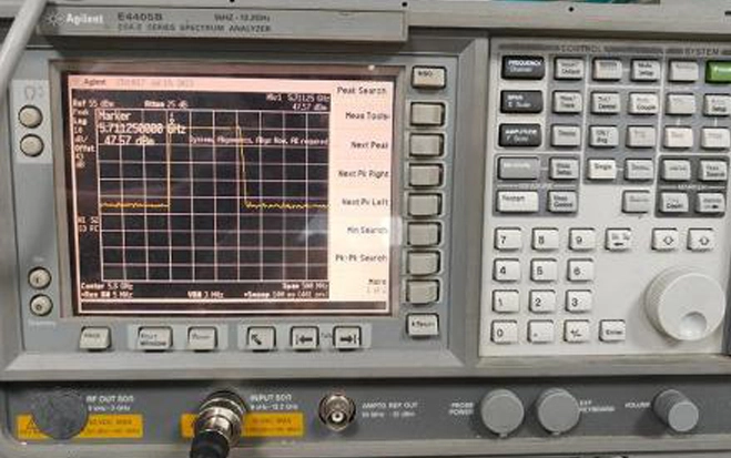
Every assembly is swept on a calibrated VNA to verify insertion loss, return loss, and VSWR across the specified frequency band, ensuring no impedance discontinuities at the connector joints.
3. Forming & Dimensional Verification
Custom-formed assemblies are verified against CAD models or physical templates to guarantee that the bent geometry matches the exact internal routing requirements of the customer's enclosure.
4. Environmental & Mechanical Testing
Assemblies undergo thermal shock testing to ensure the PTFE dielectric and solder joints do not crack under extreme temperature cycling, as well as pull-force testing to verify mechanical retention.
Standard Packaging: Individually wrapped in protective foam or PE bags to prevent scratching of the copper plating and protect connector interfaces.
Labeling: Clearly tagged with connector types, cable specification, length, and impedance.
Lead Time: Standard configurations ship within 48 hours. Custom-formed assemblies typically require 5–7 business days for forming and testing.
MOQ: Flexible MOQs. Low quantities accepted for prototyping; volume discounts applied for production runs.
Q1: What is the difference between RG402, RG405, and 0.086 semi-rigid cables?
A: The primary difference is the outer diameter and frequency capability. RG402 (0.141") is the most common, offering a great balance of low loss and manageable bend radius. RG405 (0.086") is thinner and more flexible, ideal for tight spaces. 0.086" precision variants often use specialized dielectrics to support frequencies up to 26.5 GHz or higher.
Q2: Can I bend semi-rigid cable by hand?
A: Yes, but it requires proper technique and ideally a semi-rigid forming tool or mandrel. Bending by hand without support can kink the solid copper tube, which will permanently damage the cable and ruin the impedance. Once bent, it cannot be easily straightened without risking damage.
Q3: What is the advantage of a Panel Mount N-Type connector?
A: A Panel Mount connector features a threaded barrel, hex nut, and washers, allowing it to be permanently secured through a hole in a metal chassis. This provides a robust, grounded external interface and prevents the connector from being pushed into the enclosure during mating.
Q4: Are UHF (PL-259/SO-239) connectors suitable for high-frequency semi-rigid applications?
A: UHF connectors are non-constant impedance and are generally recommended for frequencies up to 300 MHz. For VHF/UHF and microwave frequencies (above 500 MHz), we recommend using N-Type or SMA connectors with semi-rigid cable to maintain signal integrity.
Use Proper Forming Tools: Never bend semi-rigid cable over a sharp edge. Always use a bending block or mandrel sized for the specific cable diameter to prevent kinking and dielectric deformation.
Torque Specifications: When mating threaded connectors (N, SMA, TNC), always use a calibrated torque wrench. Over-torquing can distort the connector body, while under-torquing can lead to poor shielding and PIM (Passive Intermodulation) issues.
Avoid Repeated Bending: Semi-rigid cable is designed to be formed once. Repeatedly bending the same section back and forth will cause work-hardening and eventual fracture of the solid copper outer conductor.
Protect the Copper Plating: Handle the cable with clean gloves if possible. Oils and acids from bare hands can tarnish the copper plating over time. Store in a dry environment to prevent oxidation.
 English