en
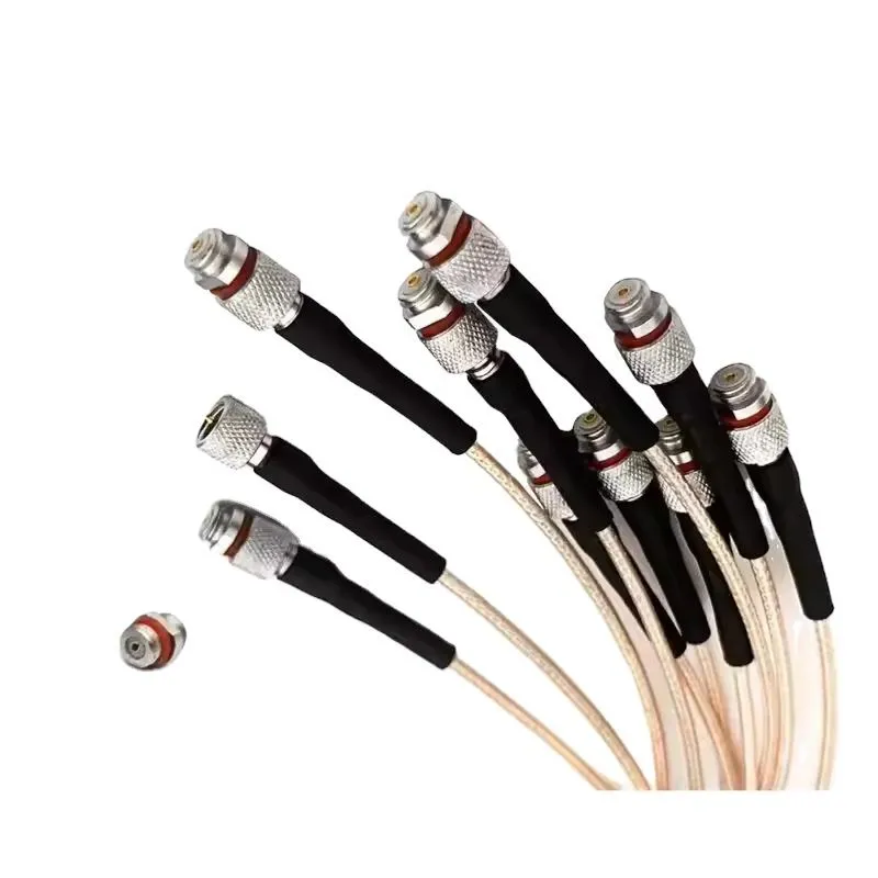
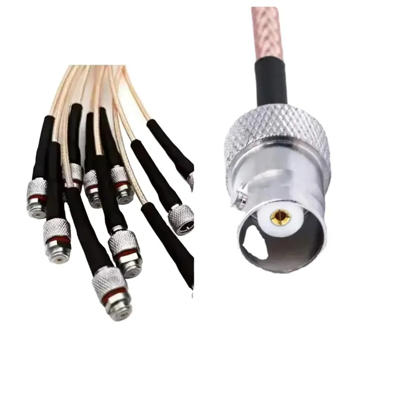
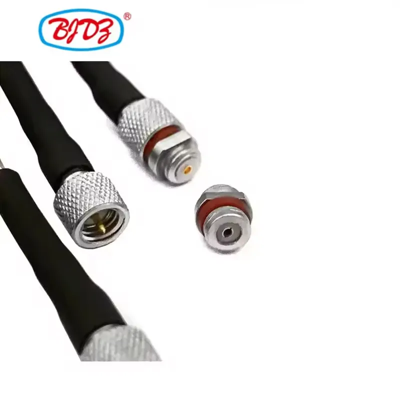
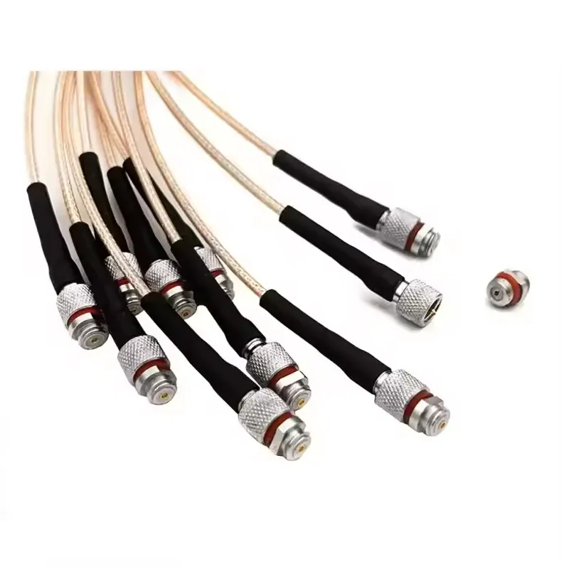
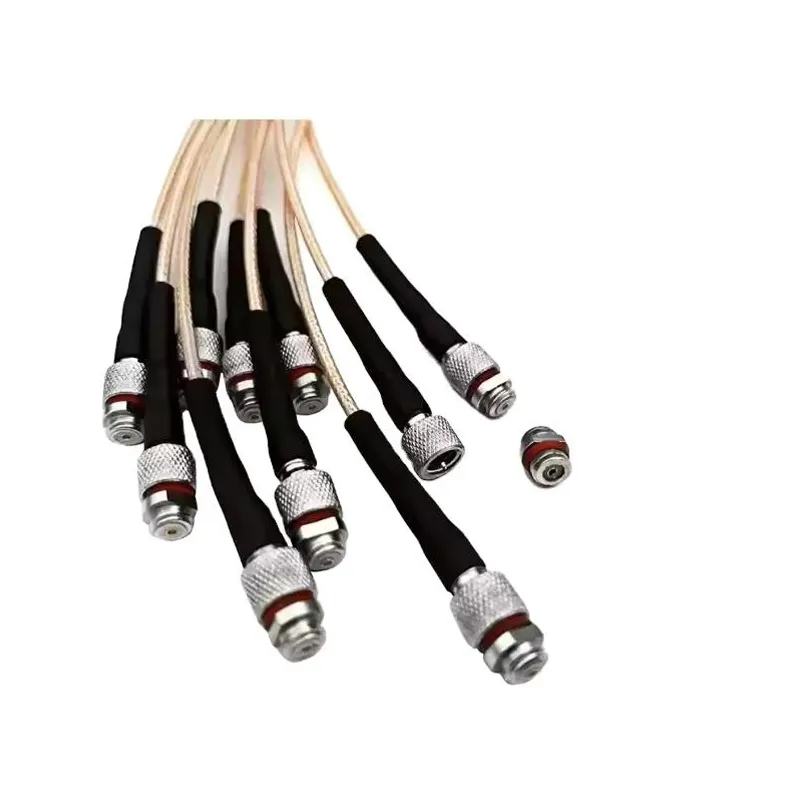
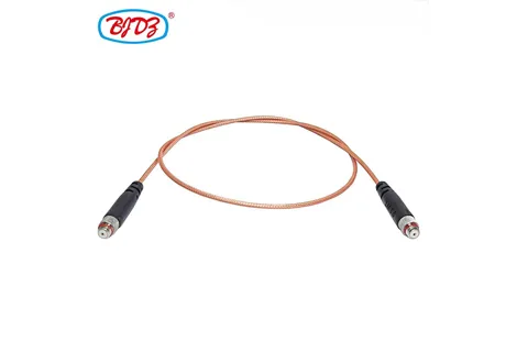
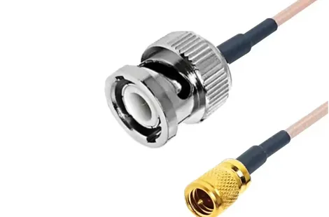
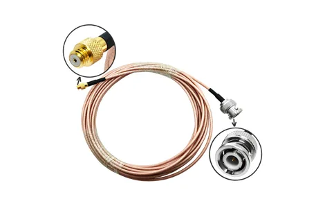
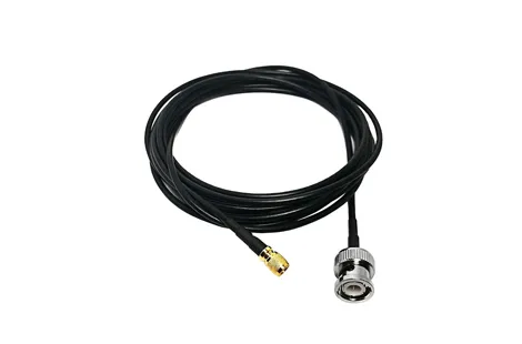
This specialized BNC Female to 10-32 UNF Female cable assembly is engineered to bridge standard test instrumentation with industrial and aerospace dynamic sensors. The 10-32 Female jack (commonly referred to as a "Microdot" style thread) is the standard interface for connecting IEPE/ICP accelerometers, piezoelectric force transducers, and vibration sensors. The BNC Female jack connects to standard data acquisition (DAQ) systems, oscilloscopes, and dynamic signal analyzers.
Utilizing RG178 PTFE coaxial cable, this assembly provides high flexibility, a micro-thin profile (~1.8mm OD), and high-temperature resistance, suitable for tight spaces and harsh testing environments.
Note on IEPE/ICP Power: This cable is designed to carry both the AC dynamic signal and the DC bias power (typically 2mA to 20mA at 24VDC) required to power active IEPE/ICP sensors. The solid PTFE dielectric and silver-plated conductors ensure stable power delivery and signal integrity.
Parameter | Specification |
Impedance | 50 Ohm (Nominal) |
Connector A | BNC Female Jack (Receptacle) Bayonet coupling Nickel/Gold-plated brass, PTFE dielectric |
Connector B | 10-32 UNF Female Jack (Microdot Style) #10-32 threaded coupling Gold-plated beryllium copper contact |
Cable Type | RG178/U (Ultra-thin, high-flex, high-temp) |
Cable Construction | Center: Silver-plated copper-clad steel (7/0.102mm) Dielectric: Extruded PTFE (0.84mm OD) Shield: Silver-plated copper braid (>95% coverage) Jacket: FEP (Teflon) or PVC |
Outer Diameter (OD) | ~1.80 mm (0.071 inches) |
Temperature Rating | -55°C to +200°C (with FEP/PTFE jacket); -40°C to +85°C (with PVC jacket) |
Capacitance | 95 pF/m |
Voltage Rating | 150 VAC max (Handles standard 24VDC IEPE bias voltage) |
VSWR | ≤ 1.30:1 (DC to 3 GHz) |
Standard Lengths | 0.5m, 1m, 2m, 3m, 5m (Custom lengths available) |
Precision 10-32 UNF Thread: The 10-32 Female connector is machined to exact UNF tolerances to ensure secure mating with standard sensor mounting studs, preventing cross-threading and ensuring a reliable electrical and mechanical ground.
Ultra-Thin RG178 to Prevent Mass Loading: In high-frequency vibration testing, stiff cables can alter the resonant frequency of the test structure (mass loading). The 1.8mm ultra-thin and highly flexible RG178 minimizes cable stiffness, ensuring accurate vibration measurements without cable-induced artifacts.
High-Temperature PTFE/FEP Materials: The PTFE dielectric and FEP jacket on the RG178 cable allow the assembly to withstand continuous temperatures up to 200°C, making it suitable for high-heat environments such as engine test cells or industrial ovens.
Low Capacitance for Signal Integrity: RG178’s low capacitance (95 pF/m) prevents signal attenuation and preserves high-frequency transients required for accurate shock and vibration analysis.
Industry / Field | Specific Use Case |
Aerospace & Defense | Routing sensor signals from turbine blades or airframe flutter tests to DAQ systems. |
Automotive NVH Testing | Connecting accelerometers to engine blocks or exhaust manifolds for Noise, Vibration, and Harshness analysis. |
Industrial Maintenance | Extending the reach of permanently mounted vibration sensors on motors and gearboxes to external data loggers. |
Structural Health Monitoring | Modal analysis and impact testing on bridges, wind turbine blades, and civil structures. |
Acoustics & Sonar | Interconnecting hydrophones and dynamic microphones to audio analyzers. |
Thread Gauge Verification: Every 10-32 Female connector is verified with calibrated Go/No-Go ring gauges to guarantee precise mating with standard sensor studs.
High-Potential (Hi-Pot) & Insulation Resistance Testing: The cable is Hi-Pot tested at 500VDC to ensure the PTFE dielectric has no micro-punctures, preventing short circuits that could damage DAQ power supplies.
Flex-Life & Strain Relief: Molded strain relief boots are applied at both connector junctions. The assembly undergoes cyclic bend testing to ensure the silver-plated shield does not fatigue under repeated routing.
Contact Inspection: The center pin of the 10-32 connector is gold-plated to prevent oxidation, which can introduce contact resistance and noise into low-level sensor signals.
Standard Packaging: Coiled and sealed in anti-static, moisture-barrier bags.
Labeling: Tagged with "BNC(F) to 10-32(F) | RG178 | [Length]".
Lead Time: Standard lengths ship within 24 hours. Custom lengths take 3–5 days.
MOQ: 1 piece for stock; 10 pieces for custom lengths.
Q1: What is the difference between 10-32 and M6 threads?
A: They are similar but NOT identical.
Q2: Can this cable power an IEPE/ICP sensor?
A: Yes. This cable is designed to carry the standard 2mA–20mA constant current DC bias (typically 24VDC) required to power the internal amplifier of IEPE/ICP sensors, while simultaneously carrying the AC vibration signal.
Q3: Is RG178 better than RG174 for sensor applications?
A: Yes. RG174 uses a solid PE dielectric and a thicker PVC jacket (2.8mm OD), making it stiffer and less heat-resistant. RG178 uses a PTFE dielectric, making it thinner (1.8mm), more flexible, and capable of surviving up to 200°C.
Q4: Will the BNC Female end plug into my DAQ system?
A: Yes. The BNC Female jack is designed to plug directly into the standard BNC Male input ports found on oscilloscopes, spectrum analyzers, and DAQ chassis.
Use a Torque Wrench: When attaching the 10-32 Female connector to the sensor stud, use a miniature torque wrench (typically set to 15 to 20 in-lbs or 1.7 to 2.3 N·m). Hand-tightening can cause poor grounding; over-tightening can damage the sensor stud.
Maintain Bend Radius: Maintain a minimum bend radius of 10mm to prevent the silver-plated copper-clad steel center conductor from fatiguing or snapping.
Clean Mating Surfaces: Before connecting the 10-32 connector, wipe both the sensor mounting base and the connector face with isopropyl alcohol to ensure a clean electrical ground path and prevent mains hum interference.
 English