en
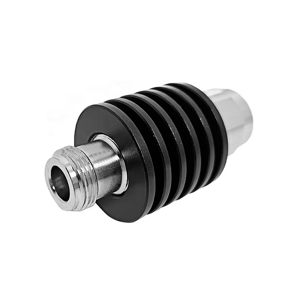
In wireless communications, test and measurement, the N Attenuator is an indispensable RF component used to reduce signal amplitude to meet specific application requirements. It is available as fixed attenuators, variable attenuators, and electronically adjustable attenuators.
| Plating | Nickel or Tri-Metal plated |
| Material | Copper |
| Insulator | PTFE/Plastic |
| Certificate | CE/FCC/ROHS/IS09001:2000. |
| Impedance | 50Ω |
| Frequency | 0-3GHz |
| vSWR | 1.15+0.02f |
| Insulation Resistance | 5000MΩ |
| Durability | 500 cycles |
| Describe | Attenuator |
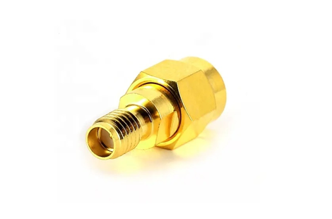
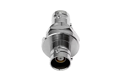
Frequency response: refers to the frequency bandwidth, generally expressed in megahertz (MHz) or gigahertz (GHz). The attenuation range refers to the attenuation ratio, generally ranging from 3dB, 10dB, 14dB, and 20dB, with a maximum of 110dB. The connector forms are divided into BNC type, N type, TNC type, SMA type, SMC type, etc., and the connector shape has two types: yin and yang. There are multiple requirements for attenuation indicators, mainly including attenuation accuracy, withstand power, characteristic impedance, reliability, repeatability, etc.
 English