en
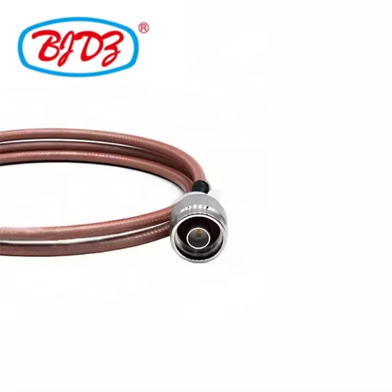
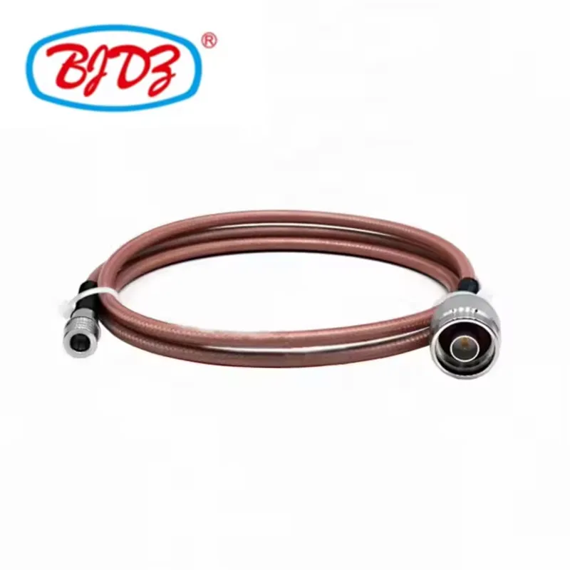
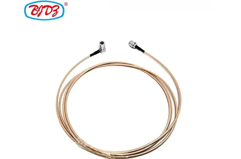
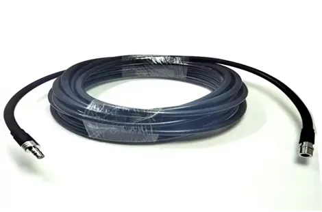
Designed for demanding high-frequency and high-reliability environments, this QMA Male to N Type Male RF Coaxial Cable Assembly bridges the gap between high-density, quick-lock indoor equipment and robust, weather-sealed outdoor or macro-level RF infrastructure.
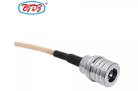
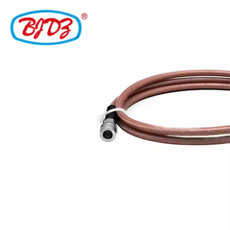
The QMA Male connector features a push-pull quick-lock mechanism that allows for rapid mating in tight, high-density rack spaces without the need for a torque wrench. The N Type Male connector provides a rugged, threaded, and weatherproof interface universally trusted in base stations, broadcast antennas, and test & measurement equipment.
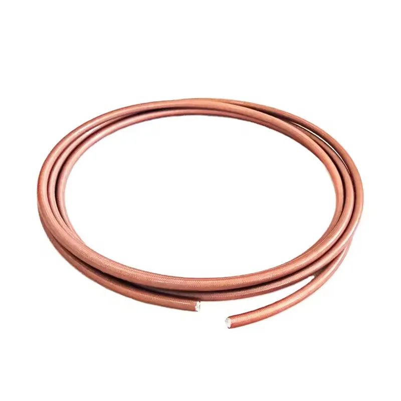
Available with either RG142 (solid center conductor) or RG400 (stranded, high-flex center conductor) micro-coaxial cable, this assembly utilizes a high-temperature PTFE dielectric and double silver-plated copper braid shielding wrapped in an FEP (Teflon) jacket. This construction ensures exceptional thermal stability (up to 200°C), superior EMI/RFI shielding (>90 dB), and excellent phase stability. Manufactured directly in our ISO-certified facility, every assembly is 100% VNA-tested to guarantee optimal VSWR and insertion loss performance up to 11 GHz (standard) or 18 GHz (precision).
Parameter | Specification |
Impedance | 50 Ohm |
Connector A | QMA Male (Plug)• Quick-lock push-pull coupling• Brass body, gold-plated contact• PTFE dielectric |
Connector B | N Type Male (Plug)• Threaded coupling (5/8"-24 UNEF)• Brass body, gold-plated contact• PTFE dielectric, weatherproof seal |
Cable Type | RG142 (Solid Conductor) or RG400 (Stranded Conductor)• Double silver-plated copper braid shield• FEP (Teflon) outer jacket |
Cable OD | 4.95 mm (0.195") |
Frequency Range | DC to 11 GHz (Standard N-Type)DC to 18 GHz (Precision N-Type option) |
VSWR | ≤ 1.20:1 (DC – 6 GHz)≤ 1.35:1 (6 – 11 GHz) |
Insertion Loss | ≤ 0.35 dB @ 2.4 GHz (1m assembly)≤ 0.85 dB @ 6.0 GHz (1m assembly) |
Shielding Effectiveness | > 90 dB (up to 10 GHz) |
Mating Cycles | QMA: 100 min / N Type: 500 min |
Temperature Rating | -55°C to +165°C (Connector)-55°C to +200°C (RG142/RG400 Cable) |
Bend Radius | 25.0 mm (1.0") minimum static |
Compliance | RoHS 2.0, REACH, MIL-DTL-17 (Cable equivalent) |
Parameter | RG142 | RG400 |
Center Conductor | Solid SPCCS (Silver-Plated Copper-Clad Steel) | 7-Strand SPCCS (High-Flex) |
Dielectric | Solid PTFE, 2.95mm OD | Solid PTFE, 2.95mm OD |
Inner Shield | Silver-Plated Copper Braid | Silver-Plated Copper Braid |
Outer Shield | Silver-Plated Copper Braid | Silver-Plated Copper Braid |
Jacket | FEP (Teflon), 4.95mm OD | FEP (Teflon), 4.95mm OD |
Velocity of Propagation | 69.5% | 69.5% |
Attenuation @ 1 GHz | 0.65 dB/m | 0.65 dB/m |
Attenuation @ 4 GHz | 1.35 dB/m | 1.35 dB/m |
Attenuation @ 10 GHz | 2.25 dB/m | 2.25 dB/m |
Flexibility | Low (Semi-Rigid) | High (Flexible) |
Industry / Field | Specific Use Case |
Telecom & Base Stations | Jumpers connecting indoor BTS/RRU equipment (QMA) to outdoor tower-top antennas or surge protectors (N-Type). |
Test & Measurement | High-reliability test port cables linking VNA (Vector Network Analyzer) or spectrum analyzer ports to DUT fixtures. |
Military & Aerospace | Avionics and radar system routing where high-temperature FEP jackets and double-shielding are mandatory. |
Broadcast & Satellite | Linking LNBs, modulators, and high-power RF amplifiers in broadcast racks. |
Medical Imaging (MRI) | Routing RF signals in environments requiring non-magnetic, high-temp, and low-outgassing Teflon cables (using non-magnetic connector options). |
1. QMA Quick-Lock High-Density Interface
The QMA connector was developed specifically to solve the space and time constraints of standard SMA interfaces. Its push-pull snap-on mechanism allows for blind mating and requires zero rotational clearance, making it ideal for high-density telecom racks, server blade backplanes, and multi-channel test fixtures where a wrench simply cannot fit.
2. N-Type Ruggedness & Power Handling
The Type N connector is the industry standard for macro-RF, outdoor antennas, and high-power amplifiers. Its robust threaded coupling ensures a vibration-proof connection, while the integrated environmental seal protects against moisture ingress. The larger contact size of the N-Type allows for significantly higher power handling compared to SMA or QMA interfaces.
3. RG142 vs. RG400: Choosing the Right Cable
While both cables share the same 4.95mm OD, PTFE dielectric, and double-shield construction, their core difference dictates their application:
• RG142 (Solid Conductor): Features a solid silver-plated copper-clad steel (SPCCS) center conductor. It offers slightly better phase stability and is ideal for fixed installations where the cable will be bent once and left in place (semi-rigid behavior).
• RG400 (Stranded Conductor): Features a 7-strand SPCCS center conductor. It is highly flexible and designed for applications requiring repeated bending, routing through tight hinges, or use in portable test equipment.
4. Double-Shielded High-Temperature Construction
The combination of a solid PTFE dielectric and a double silver-plated copper braid provides two massive advantages:
• Thermal Resilience: The cable can withstand extreme heat (up to 200°C), making it safe to route near high-power amplifiers, engines, or industrial ovens without melting or degrading.
• Ultra-Low Interference: The dense double-braid shield provides >90 dB of shielding effectiveness, preventing external EMI/RFI from corrupting sensitive RF signals and preventing signal leakage.
Manufacturing & Quality Assurance
• Precision Hex-Crimping: We use calibrated, MIL-spec hex-crimp dies specifically sized for the RG142/RG400 double-braid ferrule, ensuring a gas-tight, mechanically unbreakable connection.
• Gold-Plated Contacts: All QMA and N-Type center pins feature thick hard-gold plating over a nickel underlay for ultra-low contact resistance and maximum corrosion resistance.
• 100% VNA Electrical Testing: Every finished assembly is swept on a calibrated Vector Network Analyzer from DC to 11 GHz (or 18 GHz) to verify Return Loss and Insertion Loss. Test reports can be provided per serial number upon request.
• Mechanical Pull-Test: Random batch samples undergo a minimum 100 N axial pull test to validate the structural integrity of the heavy-duty N-Type crimp ferrule.
Option | Choices |
Cable Selection | RG142 (Semi-Rigid) / RG400 (High-Flex) |
Cable Length | 30cm, 50cm, 1m, 2m, 5m, Custom |
QMA Orientation | Straight (Standard) / 90° Right Angle |
N-Type Orientation | Straight (Standard) / 90° Right Angle |
Connector Plating | Gold over Nickel (Standard) / Tri-Metal (Silver-White Bronze for Low PIM) |
Boots & Sleeving | Optional heat shrink boots, braided metallic overbraid for armor |
Q1: Should I choose RG142 or RG400 for my application?
If the cable will be routed once inside an equipment rack and left undisturbed, RG142 is excellent and cost-effective. If the cable will be used as a portable test lead, routed through moving parts, or frequently coiled and uncoiled, you must choose RG400 to prevent the solid center conductor from snapping due to metal fatigue.
Q2: Can I use this assembly outdoors?
The N Type Male connector is inherently weatherproof when properly mated and tightened. However, the QMA connector is generally designed for indoor/panel use. If the QMA end will be exposed to the elements, we recommend using a heat-shrink weatherproof boot or specifying a sealed QMA variant.
Q3: What is the maximum power handling of this cable assembly?
The N-Type connector can handle up to 1,500W at 1 GHz. However, the limiting factor is the RG142/RG400 cable and the QMA connector. At 1 GHz, the assembly can safely handle approximately 300W CW (Continuous Wave). At 10 GHz, this drops to approximately 80W.
Q4: How tight should I torque the N-Type connector?
Standard N-Type connectors should be tightened to 1.36 N·m (12 in-lbs) using a proper torque wrench. Overtightening can damage the internal PTFE dielectric and degrade VSWR.
1. QMA Mating: Push the QMA male plug straight into the QMA female jack until you hear/feel a distinct "click." To unmating, pull back the outer sliding release sleeve and pull straight out. Never twist or rotate the QMA connector.
2. N-Type Threading: Hand-thread the N-Type coupling nut first to avoid cross-threading. Once seated, use a 5/8" torque wrench to tighten to 1.36 N·m.
3. Bend Radius Management: Maintain a minimum static bend radius of 25mm (1 inch) for RG142/RG400. Sharp bends will deform the PTFE dielectric, causing localized impedance mismatches and severe VSWR spikes.
4. Environmental Protection: If the N-Type connection is used outdoors, wrap the mated interface with high-quality self-amalgamating silicone tape to prevent moisture ingress and corrosion over time.
 English