en
Meta Title (SEO):
Motorola BNC Female to Service Port Test Cable | RG316 50Ω RF Jumper for Radio Programming, Field Diagnostics, and Fleet Maintenance
Meta Description (SEO):
Precision RG316 pigtail cable with BNC female to Motorola proprietary service connector. Engineered for 50Ω radio testing, firmware updates, and field diagnostics. MIL-STD durability, 3 GHz bandwidth, and keyed connector alignment. Ships with calibration certificate.
Purpose-Built for Motorola Radio Service & Diagnostics
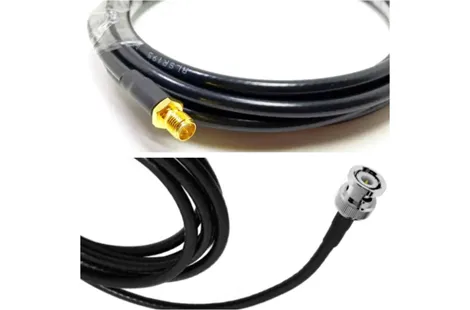
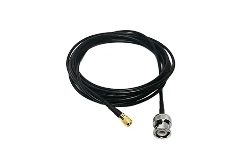
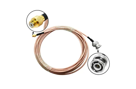
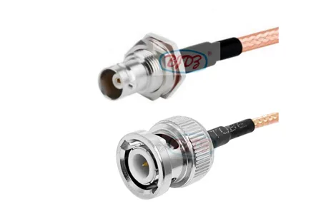
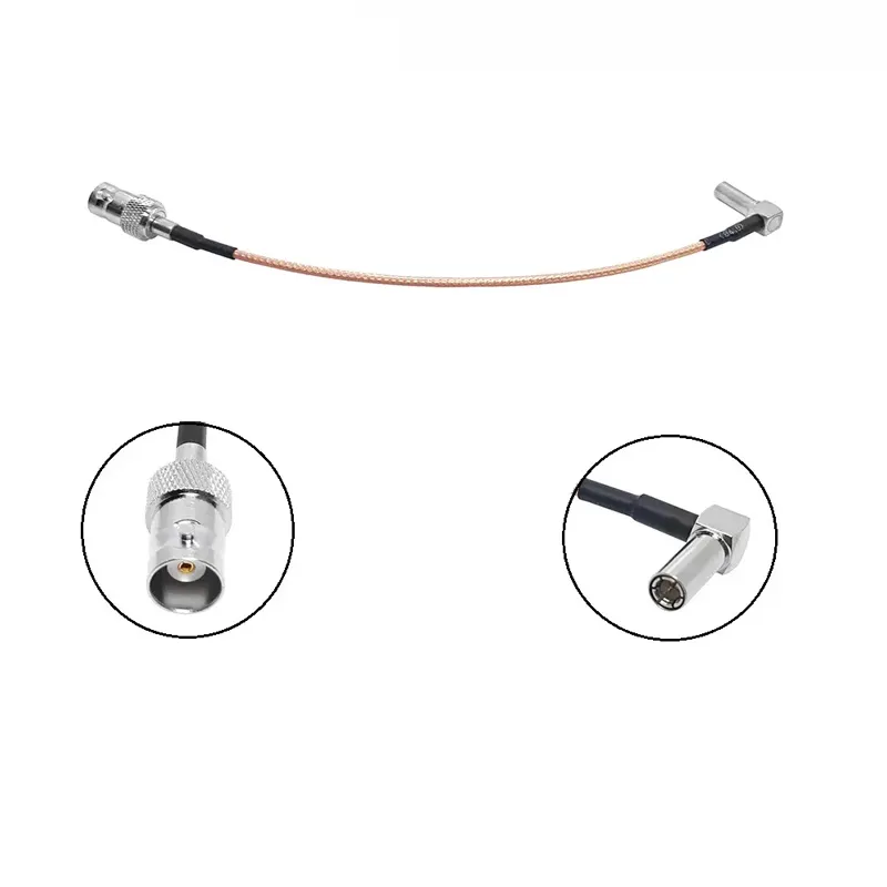
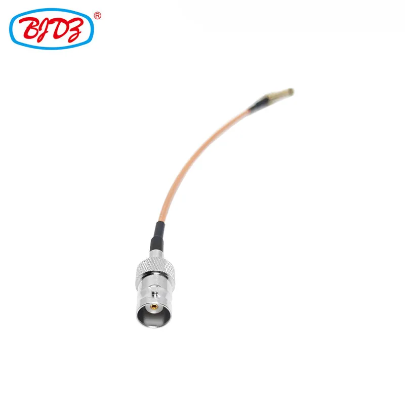
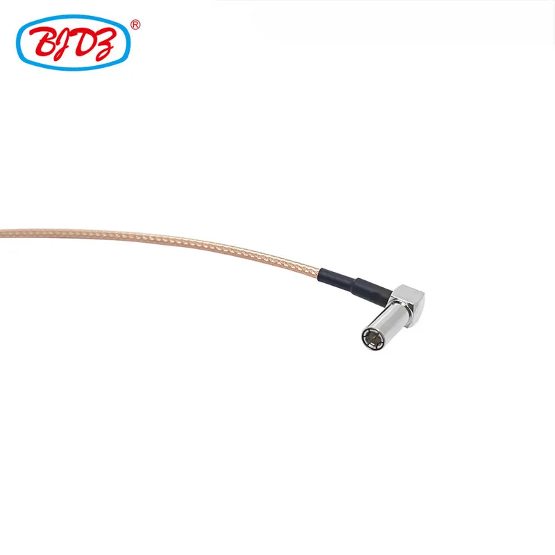
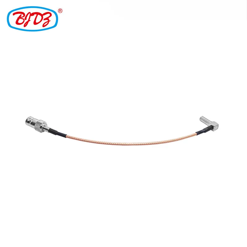
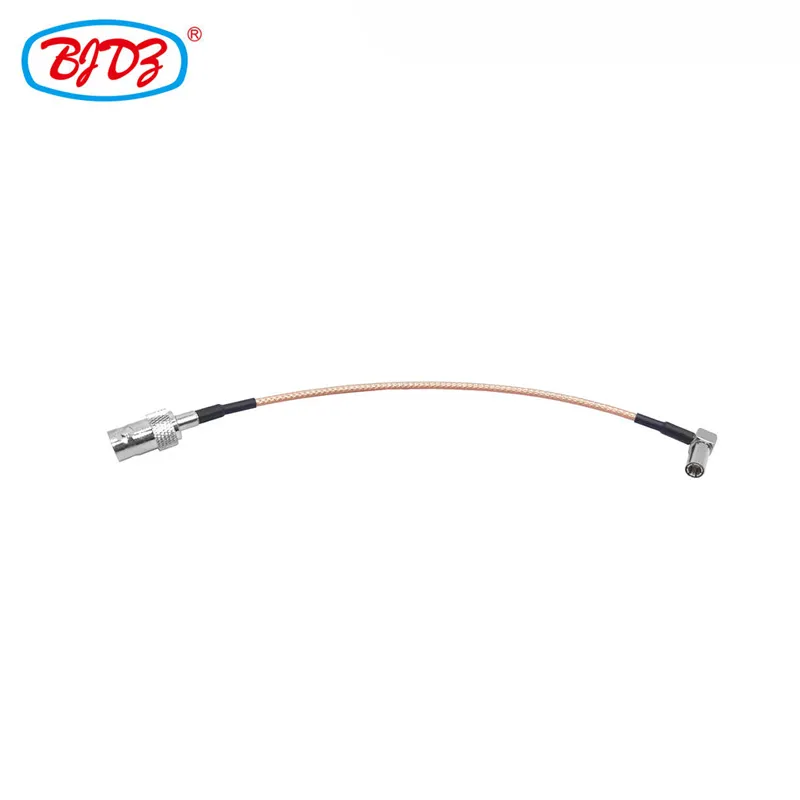
This RG316 pigtail jumper connects standard test equipment (via BNC female) to Motorola proprietary service ports found on two-way radios (e.g., MOTOTRBO, APX, XTS series). Designed for 50Ω RF systems, it ensures signal integrity during firmware updates, audio testing, and RF diagnostics with VSWR ≤ 1.2:1 and ≤ 0.45 dB loss @ 1 GHz. The keyed Motorola connector prevents misalignment, while RG316’s ruggedized construction withstands field abuse. Critical: Only compatible with Motorola radios requiring service-port access (not standard SMA/BNC interfaces).
Parameter | Specification |
Cable Type | RG316 (50Ω, 1.8 mm diameter) |
Impedance | 50 Ohm (Standard for two-way radio systems) |
Frequency Range | DC to 3 GHz (Supports VHF/UHF, TETRA, P25, and LTE bands) |
Insertion Loss | ≤ 0.45 dB/m @ 1 GHz; ≤ 0.85 dB/m @ 2.5 GHz |
VSWR | ≤ 1.2:1 (0–1 GHz); ≤ 1.35:1 (1–3 GHz) |
Connector A | BNC Female Jack Standard bayonet coupling Material: Nickel-plated brass 50Ω impedance match |
Connector B | Motorola Service Connector (Proprietary) Keyed alignment pins 6-pin configuration (varies by radio series) Gold-plated contacts Material: UV-resistant polycarbonate |
Cable Construction | Center Conductor: 30 AWG silver-plated copper Dielectric: PTFE (solid) Shielding: 95% tinned copper braid + aluminum foil Jacket: Flexible PVC (-40°C to +105°C), abrasion-resistant |
Standard Length | 30 cm (Optimized for bench testing; custom lengths: 15–100 cm) |
Key Certifications | MIL-STD-810H (vibration/shock), ROHS, Motorola Approved Service Part (ASP) |
Compatibility | MOTOTRBO (R7, SL4D), APX NEXT, XTS2500/5000, T600, and legacy service ports |
1. Proprietary Connector Precision
Motorola-specific keying ensures correct pin alignment for:
Programming data (TX/RX lines)
Power delivery (5V/12V, depending on radio)
Audio loopback testing
Critical: Prevents damage from misinsertion (common with generic adapters).
2. RG316 Durability for Field Use
20% thicker jacket than RG174 resists cuts/abrasion during vehicle installations.
PTFE dielectric maintains impedance stability under bending (tested to 5,000 flex cycles).
3. 50Ω RF Integrity for Radio Diagnostics
Matches Motorola radio impedance to avoid signal reflections during:
Transmitter power/linearity tests
Receiver sensitivity measurements
Antenna VSWR validation
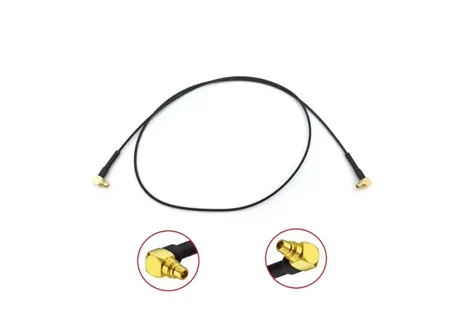
4. 90° Right Angle Design
Fits tightly behind vehicle-mounted radios (e.g., in dash compartments).
Reduces strain on service port during prolonged diagnostics.
Firmware Updates: Loading OS/software via CPS (Customer Programming Software).
Field Diagnostics: Measuring TX power, RX sensitivity, and audio distortion.
Fleet Maintenance: Testing radios in ambulances, police vehicles, and industrial fleets.
Calibration: Aligning transceivers to Motorola service manuals (e.g., TIA-603).
Emergency Repairs: Bypassing damaged internal cables during on-site fixes.
1. Motorola-Specific Validation
Tested on actual radio models (APX 8000, XTS5000) for:
Pin continuity (6 circuits verified)
Power delivery stability (5V/1A load test)
Data transfer integrity (CPS handshake validation)
2. MIL-STD Environmental Testing
Vibration: 5–500 Hz, 15 G (per MIL-STD-810H Method 514.7)
Temperature: -40°C to +85°C cycling (20 cycles, no signal degradation)
Flex Life: 5,000+ bends at 5x cable diameter radius
3. Traceable Calibration
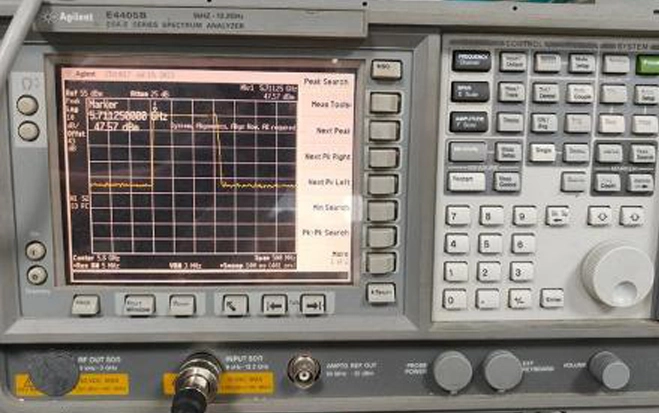
Every batch includes NIST-traceable VSWR/loss report (tested to 3 GHz).
1. Standard Packaging: Individually sealed in ESD bag with:
Connector pinout diagram (Motorola radio-specific)
Calibration certificate
Compatibility checklist (radio models/series)
2. Lead Time: 24 hours for standard 30 cm length; 3–5 days for custom lengths.
3. MOQ: 1 unit (stock); custom lengths require 5+ units.
4. Bulk Orders: Serialized for fleet management (e.g., "Fleet ID: FDNY-2024").
Q1: Which Motorola radios does this support?
A: Compatible with all Motorola radios using a 6-pin service port, including:
Q2: Can I use this for antenna testing?
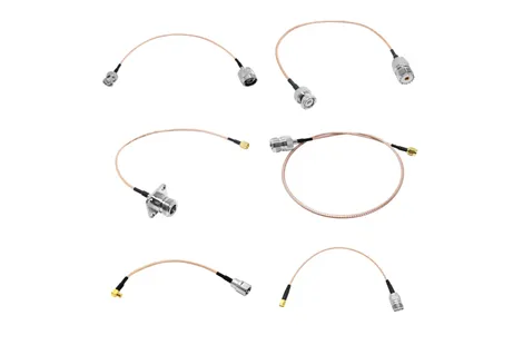
A: No. This cable connects to the service port (for programming/diagnostics), not the antenna port. For antenna testing, use a 50Ω BNC/SMA pigtail (e.g., RG316 to N-Male).
Q3: Does it supply power to the radio?
A: Yes. Delivers up to 12V/1A via pin 1 (varies by radio model—see included pinout guide). Never connect to external power sources without validation.
Q4: Is the connector keyed to prevent reverse insertion?
A: Yes. Asymmetric housing and alignment pins ensure correct orientation (prevents pin damage).
1. Verify Service Port Type: Confirm your radio uses a 6-pin Motorola service connector (not USB or mini-DIN).
2. Length Requirements:
≤ 30 cm: Ideal for bench testing (minimizes signal loss).
> 50 cm: Requires active signal conditioning for data transfers.
3. Not for Antenna Paths: This is not an antenna extension cable—using it for RF transmission risks radio damage.
Radio Series | Service Port Type | Key Requirement |
MOTOTRBO R7/SL4D | 6-pin rectangular | Supports 12V power delivery for fast CPS |
APX NEXT | 6-pin oval | Requires firmware v3.0+ for CPS handshake |
XTS5000 | 6-pin trapezoidal | Legacy CPS only (no Bluetooth passthrough) |
T600 | 6-pin circular | 5V power max (do not exceed 1A) |
Download Pinout Guide | Request Radio-Specific Quote
Includes free CPS compatibility validation with every order.
Need an antenna test cable? → Explore 50Ω BNC/SMA RF Jumpers (RG316/RG174)
 English